Switch Characteristic Tester
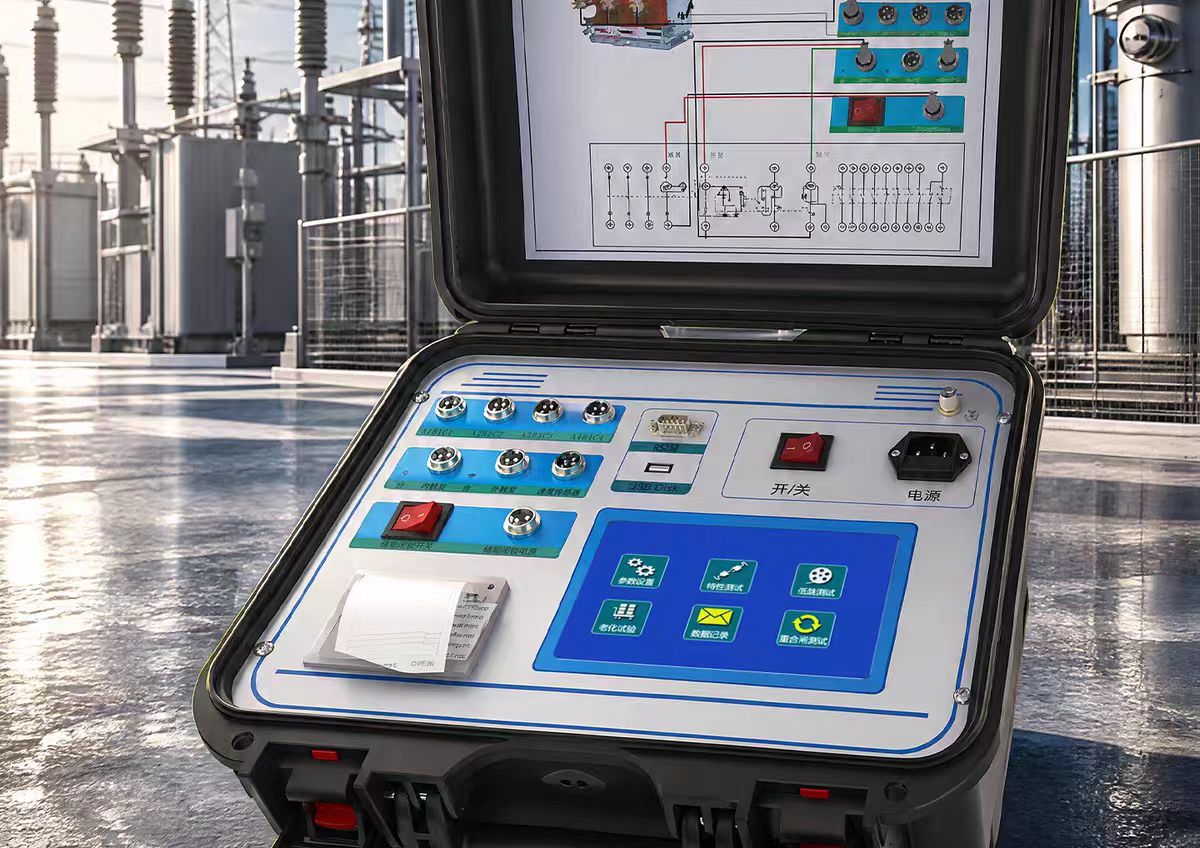
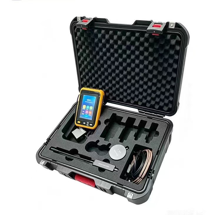
The Switch Characteristic Tester (also known as "High Voltage Switch Dynamic Characteristic Tester" or "Circuit Breaker Mechanical Characteristic Tester") is an intelligent testing instrument specifically designed to measure the mechanical operating characteristics of high-voltage circuit breakers. It is a core diagnostic tool in power systems for evaluating the operational reliability of high-voltage switchgear.
Working Principle
The Switch Characteristic Tester applies a controllable DC operating voltage to the circuit breaker under test (driving the opening/closing coil operation) and synchronously collects multiple signals to complete the measurement:
Contact Signal Acquisition: Through 12 (or more) contact channels, it monitors the on/off state changes of the main and auxiliary contacts of each phase in real time, accurately recording the closing/opening instants.
Travel/Speed Measurement: Using linear sensors, rotary sensors, or acceleration sensors, it tracks the displacement-time relationship of the moving contact in real time, calculating speed and travel parameters.
Coil Current Monitoring: A series current sampling circuit records the current waveform of the opening/closing coil, used to analyze the coil circuit status and core movement.
Data Processing: High-performance DSP or embedded industrial computer performs high-speed sampling and digital processing of the acquired signals, automatically calculating various parameters and generating waveform diagrams.
Core Measurement Parameters
Time Parameters: Inherent opening time, inherent closing time, reclose time (close-open, open-close, open-close-open), contact touch time, dead time.
Synchronization: Phase-to-phase and pole-to-pole non-synchronism during opening (closing), reflecting the consistency of three-phase operation.
Bounce Characteristics: Closing bounce time, bounce count, opening rebound amplitude; excessive bounce can easily erode contacts.
Speed Parameters: Opening speed at contact separation, closing speed at contact touch, maximum speed, average speed over specified segments.
Travel Parameters: Total travel, contact gap, overtravel, overshoot, rebound travel.
Electrical Parameters: Opening/closing coil current values and waveforms, coil resistance, minimum operating voltage.
Main Functions and Features
Full Parameter Acquisition in One Operation: A single operation of the circuit breaker yields all data and waveform diagrams including time, speed, travel, bounce, and coil current, with data and graphics displayed on the same screen.
Built-in Operating Power Supply: Integrated DC 6-270V continuously adjustable power supply (instantaneous current up to 20-30A), no external secondary power supply needed, can directly drive circuit breaker opening/closing.
Multiple Trigger Modes: Supports internal trigger (instrument's own power supply drive), external trigger (coil voltage signal acquisition), and manual trigger, adapting to different field conditions.
Low Voltage Operation Test: Automatically or manually adjusts the operating voltage step by step to determine the minimum reliable operating voltage of the circuit breaker.
Strong Anti-interference Capability: Internally equipped with electromagnetic interference absorption circuits, ensuring reliable use in 500kV substations.
Data Storage and Export: The host can store hundreds to tens of thousands of test data sets, supporting USB export and PC online analysis.
Integrated Testing: Some high-end models integrate mechanical characteristic testing with main circuit contact resistance testing (100A) in one device.
Typical Technical Parameters (using mainstream models as examples)
Table
Download as Table
Export as Image
Parameter Specification
Contact Channels 12 (6 main + 6 auxiliary)
Time Resolution 0.01ms
Time Measurement Error ±0.05%+0.1ms
Travel Resolution 0.1mm (linear sensor)
Speed Measurement Range 0.1-20m/s
Speed Error ±0.1m/s
Built-in Power Output DC 6-270V continuously adjustable, ≤20A (short-time)
External Trigger Voltage AC/DC 10-300V
Operating Temperature -20℃ to +50℃
Relative Humidity ≤90%
Applicable Switch Types
Suitable for various voltage levels of:
SF₆ circuit breakers (sulfur hexafluoride switches)
Vacuum circuit breakers
Minimum oil / bulk oil circuit breakers
GIS switchgear
Vacuum contactors
Typical Application Scenarios
Power companies: High-voltage circuit breaker acceptance tests, periodic preventive tests (according to DL/T 596 standard)
Switch manufacturers: Factory inspection, verifying whether mechanical characteristic parameters meet design requirements
Maintenance and repair: Post-overhaul re-inspection of circuit breakers, comparing historical data to judge mechanical condition degradation trends
Third-party testing institutions: Type tests and certification tests according to GB 1984, DL/T 846.3 and other standards
Rail transit / industrial and mining enterprises: Periodic testing of high-voltage switches in self-owned substations
Selection Key Points
Contact Channels: Conventional 12 channels meet most requirements; special switches (e.g., with closing resistors) need to check if more channels are supported
Sensor Configuration: Linear sensors are suitable for vacuum circuit breakers, rotary sensors for SF₆ switches; it is recommended to select based on the type of switch under test
Power Output Capability: Pay attention to output voltage range and instantaneous current to ensure it can drive the opening/closing coil of the circuit breaker under test
Anti-interference Level: For field work in 500kV and above substations, confirm anti-interference capability
Additional Functions: Whether integrated loop resistance testing, aging life testing, lockout power testing, etc. are needed
Data Management: Choose storage capacity and data export methods based on archiving requirements