Winding Deformation Tester
Winding Deformation Tester (also known as Transformer Winding Deformation Tester, Frequency Response Analyzer/FRA) is a specialized diagnostic device used to detect mechanical deformation of power transformer windings. It scans the amplitude-frequency characteristic curve of the winding using Frequency Response Analysis (FRA), enabling the detection of issues such as winding distortion, bulging, displacement, and inter-turn short circuits without the need for lifting the transformer cover. It serves as the "structural doctor" ensuring the safe operation of transformers.
Core Principle – Frequency Response Analysis (FRA)
Under high-frequency voltage excitation, each transformer winding can be equivalent to a passive linear two-port network composed of distributed parameters such as linear resistance, inductance (mutual inductance), and capacitance. Its internal characteristics can be described by the transfer function H(jω).
When mechanical deformation occurs in the winding, the internal distributed inductance, capacitance, and other parameters inevitably change, causing shifts in the zeros and poles of the transfer function, resulting in identifiable deviations in the frequency response characteristic curve. The instrument performs diagnosis through the following steps:
Signal Injection: The DDS signal source injects a sinusoidal sweep excitation signal ranging from 1kHz to 2MHz (some models extend to 10Hz to 10MHz) into the winding.
Signal Acquisition: Dual-channel simultaneous acquisition of voltage signals at the excitation end and response end.
Transfer Function Calculation: Calculate the amplitude ratio of the two channel signals to generate the amplitude-frequency response curve.
Comparative Analysis: Perform correlation coefficient analysis between the current curve and the factory "fingerprint" data (longitudinal comparison) or three-phase data of the same equipment (horizontal comparison) to determine the degree of deformation.
Diagnostic Significance of Frequency Bands
Anomalies in different frequency bands reflect different types of winding defects:
Low Frequency Band (1kHz – 100kHz): Reflects overall inductance characteristics; anomalies indicate overall deformation, core displacement, or inter-turn/inter-disc short circuits.
Mid Frequency Band (100kHz – 600kHz): Sensitive to local deformation; indicates bulging, collapse, or distortion.
High Frequency Band (600kHz – 1MHz and above): Reflects inter-turn distributed parameter characteristics; anomalies indicate overall winding displacement or lead movement.
System Composition
The equipment typically consists of the following components:
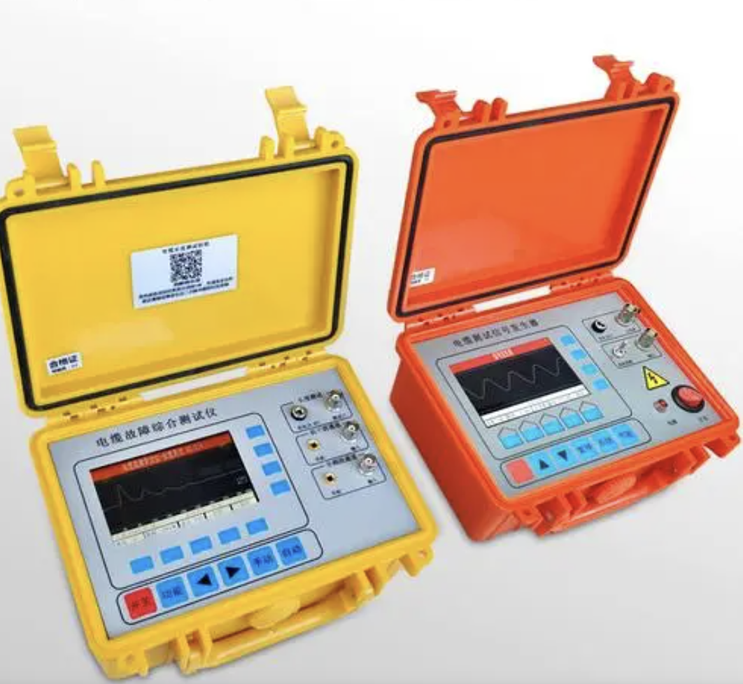
Measurement Main Unit (Black Box): Contains a built-in DDS signal generator, dual-channel high-speed acquisition module, and automatic range adjustment circuit.
Analysis Software: Installed on a laptop or the instrument's built-in touchscreen, it performs curve display, correlation coefficient calculation, deformation level determination, and report generation.
Connection Cables: Excitation cable, response cable, grounding cable, etc.
Accessories: USB/Ethernet communication cables, micro printer (built-in on some models).
Key Technical Parameters
Table
Download as Table
Export as Image
Parameter Typical Range
Sweep Frequency Range 1kHz – 2MHz (High-end: 10Hz – 10MHz)
Sweep Points 1000 – 4000 points
Frequency Accuracy ≤0.01% (some up to 0.001%)
Amplitude Measurement Range -100dB to +20dB
Amplitude Measurement Accuracy 0.1dB
Sampling Rate 20Msps – 100Msps
Quantization Resolution 12 – 16 bits
Signal Output Impedance 50Ω
Signal Input Impedance 1MΩ
Signal Output Amplitude Maximum ±5V to ±10V
Single-Phase Test Time <60 seconds to several minutes
Communication Interface USB / Ethernet / WiFi / Bluetooth
Detection Methods
In addition to the mainstream Frequency Response Analysis (FRA), there are the following auxiliary methods:
Short-Circuit Impedance Method (Reactance Method)
Measure the winding impedance or leakage reactance at 50Hz and determine deformation based on the rate of change.
Judgment thresholds: Impedance change rate ≤2% is normal; 2% – 3% indicates slight deformation; >3% indicates obvious deformation, recommending shutdown and internal inspection.
Execution standard: DL/T 1093-2008
Low-Voltage Pulse Method
Inject low-voltage pulse signals into the winding and analyze reflected waveforms to determine deformation location.
High sensitivity, but strict requirements on the test environment.
Result Judgment Standards
According to DL/T 911-2016, the degree of deformation is quantitatively determined using correlation coefficients:
Judgment Based on Correlation Coefficient R
Table
Download as Table
Export as Image
Deformation Degree Correlation Coefficient Range
Normal >0.99 (longitudinal) / >0.98 (horizontal)
Mild Deformation 0.97 – 0.99
Moderate Deformation 0.95 – 0.97
Severe Deformation <0.95
Judgment Based on Frequency-Band Correlation Coefficients
Table
Download as Table
Export as Image
Deformation Degree Criterion
Normal RLF≥2.0 and RMF≥1.0 and RHF≥0.6
Mild Deformation 2.0>RLF>1.0 or 1.0>RMF>0.6
Obvious Deformation 1.0>RLF>0.6 or RMF<0.6
Severe Deformation RLF<0.6
RLF, RMF, and RHF are the correlation coefficients for the low-frequency, mid-frequency, and high-frequency bands, respectively.
Main Application Scenarios
Before commissioning new transformers: Collect factory "fingerprint" data to establish baseline curves.
After short-circuit impacts: Mandatory testing after nearby short circuits to determine if the winding is damaged.
After transportation collisions: Detect whether vibration during transport caused winding displacement.
Routine preventive tests: Once every 1 – 3 years in normal maintenance cycles.
After winding replacement or major repair: Verify repair quality.
Renewable energy stations: Health assessment of wind/solar box transformer windings.
Applicable equipment includes oil-immersed power transformers (110kV – 1000kV), dry-type transformers, rectifier transformers, converter transformers, autotransformers, traction transformers, etc. Test Conditions and Precautions
Test Conditions
The transformer must be de-energized and reliably grounded.
Ambient temperature: -15°C to +50°C, relative humidity ≤90%.
All side leads must be disconnected; testing should be performed at the maximum tap position or a fixed tap position.
Sufficient demagnetization is required before testing; testing should not be conducted during thunderstorms.
Precautions
Test connections must be secure and reliable, and the grounding wire cross-section must meet requirements.
For multiple tests on the same transformer, the connection method should remain consistent to ensure data comparability.
Test data should be properly stored as the historical "fingerprint" archive for the equipment.
When curve anomalies occur, comprehensive judgment should be combined with auxiliary methods such as dissolved gas analysis (warning if acetylene content >5μL/L) and DC resistance testing.