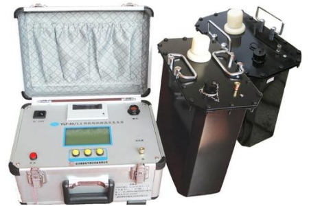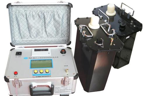
Zinc Oxide Arrester Tester
The Zinc Oxide Arrester Tester (also known as Arrester Resistive Current Tester, Intelligent Arrester Characteristics Tester) is a specialized instrument used to detect the electrical performance of zinc oxide arresters (MOA). By measuring key parameters such as leakage current and resistive current of the arrester, it can timely discover dangerous defects such as internal insulation dampness and valve plate aging. It is suitable for live or outage detection of arresters at various voltage levels.
Detection Principle
Under normal operating voltage, a zinc oxide arrester passes a small leakage current, which consists of a capacitive component and a resistive component. Under normal conditions, the resistive current is extremely small, but when the arrester valve plates age or internal moisture occurs, the resistive current significantly increases. The tester collects voltage reference signals and leakage current signals, and uses Fourier harmonic analysis technology to decompose the total current into resistive and capacitive components, thereby accurately determining the health status of the arrester.
Core Measurement Parameters
Table
Download as Table
Export as Image
Parameter Item Description
Total Current Total RMS value and peak value of arrester leakage current
Resistive Current Core indicator for judging valve plate aging and moisture level
Capacitive Current Capacitive component of total current
Resistive Current Harmonics Fundamental and 3rd to 9th harmonic content, auxiliary analysis of defect types
Power Frequency Reference Voltage Arrester reference voltage and its harmonics
Active Power Arrester power consumption
Phase Difference Phase angle difference between total voltage and total current
Voltage/Current Waveform Real waveform display for intuitive analysis
Voltage Reference Signal Sampling Methods
The tester needs to obtain a voltage reference signal to accurately decompose the resistive current. Common methods include the following:
Table
Download as Table
Export as Image
Sampling Method Principle Features
PT Secondary Side Sampling (Wired Synchronization) Obtain reference voltage from the secondary side of voltage transformer Highest accuracy, but requires wiring, transmission distance generally about 40 meters
Wireless Synchronization Transmit PT signal via wireless module Safe and convenient operation, transmission distance up to 400~1500 meters or more
Induction Plate Method Use electric field induction plate to obtain bus voltage phase information No wiring required, safe and fast operation, accuracy close to secondary method
Current Analysis Method (No Voltage) Calculate resistive current only through FFT analysis of current signal Simplest operation, but relatively lower accuracy
Key Technical Parameters
Table
Download as Table
Export as Image
Parameter Item Typical Specification
Total Current Measurement Range 0~20mA (expandable)
Resistive Current Measurement Range 0~20mA
Capacitive Current Measurement Range 0~20mA
Voltage Acquisition Range 30~250V (expandable)
Electric Field Strength Input Range 30kV/m~300kV/m (optional)
Current Measurement Accuracy ±2%~±5% of reading (when total current >100μA)
Voltage Measurement Accuracy ±2%~±5% of reading (when reference voltage >30V)
Harmonic Analysis Fundamental and 3rd to 9th harmonics
Wired Synchronization Distance About 40 meters
Wireless Synchronization Distance 400~1500 meters or more (expandable to 5000 meters)
Power Supply Built-in lithium battery, continuous operation for 4~8 hours
Data Storage Can store 100~210 sets of data, supports U-disk export
Main Functional Features
Live/Outage Compatibility: Can be used for online detection during equipment operation, and also for use during outage maintenance
Three-Phase Simultaneous Measurement: Supports simultaneous testing of three-phase current and three-phase voltage, greatly improving work efficiency
Interphase Interference Compensation: Built-in anti-interference calculation and angle compensation functions (such as automatic side compensation) to solve three-phase mutual interference problems at 220kV and above voltage levels
Digital Waveform Analysis: Uses high-speed sampling and digital signal processing technology, combined with software anti-interference methods such as harmonic analysis and digital filtering, to ensure accurate and stable measurement results
Data Management: Built-in calendar clock, large-capacity storage, U-disk export to Word files, some models support Bluetooth APP mobile phone control and data upload
Safe and Reliable: The instrument internally only carries weak electricity (generally not exceeding 12V), and current and voltage sensors are completely isolated
Implementation Standards
DL/T 474.5-2018 "Guide for Implementation of On-site Insulation Tests Part 5: Arrester Tests"
DL/T 987-2005 "General Technical Conditions for Zinc Oxide Arrester Resistive Current Testers"
DL/T 596 "Preventive Test Regulations for Electric Power Equipment"