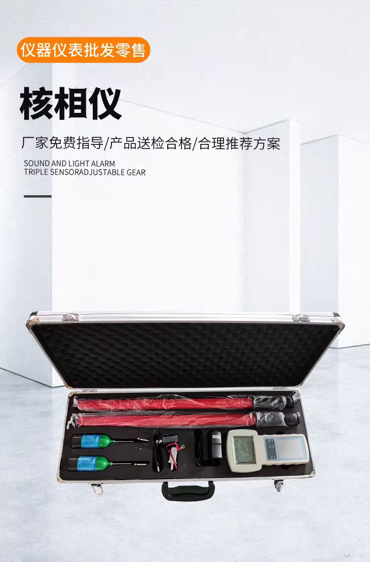
Partial Discharge Detector
The partial discharge detector (PD detector) is a precision instrument specifically used to detect insulation defects in high-voltage electrical equipment. Partial discharge is a weak discharge triggered by bubbles, cracks, or metal impurities inside insulation under high electric fields. In the initial stage, its energy is extremely small and invisible to the naked eye, but it continuously erodes the insulation structure and may eventually lead to equipment breakdown and large-scale power outages. The PD detector captures signals such as electromagnetic waves, ultrasonic waves, and transient voltages generated by the discharge, enabling quantitative testing of equipment insulation status and defect localization.
Core Detection Technologies
At present, multiple detection technologies are mainly used, and in practical applications, multiple technologies are often integrated and cross-verified to improve accuracy:
Table
Download as table
Export as image
Technology Detection Frequency Band Features
Pulse Current Method (ERA) 10kHz~300kHz Based on IEC 60270 standard, can measure apparent discharge magnitude (pC), highest accuracy, is the benchmark method
Ultra-High Frequency Method (UHF) 300MHz~3GHz Strong anti-interference capability, can penetrate metal enclosures, suitable for internal discharge detection in closed equipment such as GIS
Ultrasonic Method (AE/UA) 20kHz~300kHz Not affected by electromagnetic fields, excels at discharge point localization, suitable for external detection of transformers and switchgear
Transient Earth Voltage Method (TEV) 3MHz~100MHz Induces pulse voltage through the cabinet surface, easy to install, suitable for live detection of switchgear
High-Frequency Current Method (HFCT) 100kHz~100MHz Clamp-on installation on cable grounding wire, suitable for online cable monitoring
Acoustic Imaging Technology Ultrasonic Array Superimposes sound source position onto optical images, enabling visual rapid localization of discharge points
System Composition
A complete PD detection system usually includes:
Detection Host: Responsible for signal acquisition, amplification, filtering, A/D conversion, and data processing, equipped with touchscreen display
Sensor Set: UHF antennas, ultrasonic probes, TEV sensors, HFCT clamp-on current transformers, etc., selected according to the equipment under test
Synchronization Unit: Supports internal synchronization, external synchronization, wired/wireless synchronization, phase accuracy ≤0.1°
Calibration Pulse Generator: Used for system sensitivity calibration
Data Analysis Software: Generates PRPD/PRPS spectra, supports automatic discharge type identification and trend analysis
📐 Key Technical Parameters
Table
Download as table
Export as image
Parameter Typical Range
Detection Sensitivity Pulse current method can reach 0.02pC~0.1pC; UHF/TEV/HFCT methods ≤0.5pC~1pC
Sampling Rate 100MS/s~2GS/s
Sampling Accuracy 8Bit / 12Bit / 14Bit / 16Bit
Dynamic Range Up to 120dB
Linearity Error ≤±10%
Localization Accuracy Acoustic imaging can reach <1cm; UHF/AE fusion localization ≤1m
Measurable Capacitance 6pF~250μF
Operating Temperature -20℃~+50℃
Table
Download as table
Export as image
Type Features Applicable Scenarios
Handheld Portable Weight 0.25kg~3.5kg, built-in battery, single-person operation, battery life ≥8 hours Daily inspection, troubleshooting, live detection
Benchtop Detection System Multi-channel measurement, automatic calibration, comprehensive functions Factory test, handover test, laboratory testing
Online Monitoring System 7×24-hour uninterrupted acquisition, remote data transmission, intelligent alarm Unattended substations, long-term monitoring of important equipment
Mobile Temporary Monitoring Plug and play, IP65 protection, rapid deployment and withdrawal Equipment insulation troubleshooting, warranty period assessment
Intelligent Analysis Functions
Modern PD detectors are equipped with high-performance digital processing chips and intelligent analysis systems. Core analysis tools include:
PRPD Spectrum (Phase-Resolved Partial Discharge): Presents the correlation between discharge pulse amplitude and power-frequency voltage phase in two-dimensional form, determining whether the discharge is related to power frequency
PRPS 3D Spectrum: Adds a time dimension, fully reproducing the variation pattern of discharge characteristics over time
3PARD Three-Phase Amplitude Relationship Diagram: Separates multiple simultaneously existing discharge sources
Automatic Discharge Type Identification: Combined with AI algorithms, can automatically distinguish typical discharge types such as free metal particles, floating potential bodies, insulation voids, and metal protrusions
Acoustic Imaging Localization: Through microphone arrays, superimposes sound source position in real time onto optical images, intuitively displaying discharge points like a "thermal imager"
Applicable Equipment and Application Scenarios
Power Transformers: Monitor insulation degradation of windings, cores, bushings, etc.
GIS (Gas-Insulated Switchgear): Detect discharge defects in internal insulators, contacts, and other parts
Switchgear: Monitor discharge caused by loose busbar connections, damp insulators, etc.
Power Cables: Monitor insulation status of weak points such as cable joints and terminations
Rotating Machines: Monitor stator winding insulation condition
Instrument Transformers, Surge Arresters, Capacitors, Bushings: Monitor internal insulation defects
Application stages cover the entire process of type tests, factory tests, handover tests, preventive tests, live inspections, and online monitoring.
Related Standards
IEC 60270: Benchmark standard for partial discharge measurement
IEC 62478: Standard for partial discharge detection of high-voltage equipment
GB/T 7354: National standard for partial discharge measurement
DL/T 417: Guide for on-site partial discharge measurement of power equipment
DL/T 846 Series: Technical standards for partial discharge detection instruments
🛒 Selection Key Points
Clarify Detection Method: Choose benchtop systems for offline tests, handheld devices for live inspections, and online monitoring systems for long-term monitoring
Detection Technology Selection: According to the type of equipment under test and on-site electromagnetic environment, choose a single technology or multi-technology fusion solution
Sensitivity Requirements: Pulse current method has the highest accuracy but requires power outage; UHF/TEV methods are suitable for live detection but have slightly lower sensitivity
Portability: For frequent outdoor operations, prioritize lightweight handheld designs
Software Functions: Whether it supports PRPD/PRPS spectrum analysis, automatic discharge type identification, remote data access, and intelligent alarms
Scalability: Consider the ability to subsequently add sensor channels and monitoring points