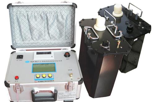
Winding Deformation Tester
The Winding Deformation Tester (full name: Transformer Winding Deformation Tester) is a specialized diagnostic instrument used to detect whether mechanical deformation has occurred inside the windings of power transformers. After a transformer experiences short-circuit current surges, transportation impacts, or long-term operational vibration, the windings may suffer permanent deformation such as twisting, bulging, or displacement. If not detected in time, this can seriously affect insulation safety and even lead to accidents. This instrument enables non-destructive testing of windings without the need to lift the transformer cover or disassemble components, making it a core device for preventive testing and post-accident diagnosis of transformers.
Working Principle
The Winding Deformation Tester primarily employs the Frequency Response Analysis (FRA) method, with its core principles as follows:
Equivalent Model: Under higher frequency voltage, each transformer winding can be considered a passive linear two-port network composed of distributed resistance, inductance (mutual inductance), capacitance, and other parameters. Its internal characteristics can be described by the transfer function H(jω).
Frequency Sweep Measurement: The instrument injects a sinusoidal excitation signal with continuously adjustable frequency (typically covering 1kHz to 2MHz or even a wider range) into the winding, while simultaneously measuring the excitation terminal voltage V1 and the response terminal voltage V2. It calculates the amplitude ratio at different frequencies and plots the amplitude-frequency response curve of the winding.
Deformation Assessment: If the winding deforms, its internal distributed inductance and capacitance parameters will inevitably change, causing shifts in the zeros and poles of the transfer function, and consequently altering the amplitude-frequency response curve. By comparing the measured curve with the factory original curve (longitudinal comparison) or with curves from similar three-phase windings (horizontal comparison), it can be determined whether the winding has deformed and the extent of the deformation.
Changes in different frequency bands reflect different types of deformation: changes in the low-frequency band (below 1kHz) are typically related to core condition or axial displacement of the winding; changes in the high-frequency band (above 100kHz) often reflect changes in distributed capacitance, commonly associated with radial deformation or inter-turn short circuits.
Main Classifications
Based on testing principles and technical approaches, winding deformation testers are divided into three categories:
Frequency Response Analysis (FRA) Testers: High sensitivity, capable of detecting minor winding deformation and changes in distributed parameters, but result analysis requires some experience and is significantly affected by on-site interference factors.
Low-Voltage Short-Circuit Impedance Method Testers: Measure the short-circuit impedance value of the transformer at low voltage, and determine deformation by comparing with nameplate values or historical data. The judgment criteria are relatively clear (typically using a change rate of ±3% as a warning value), with strong anti-interference capability, but sensitivity to minor deformation is lower than the FRA method.
Comprehensive Testers: Integrate both FRA and impedance methods into a single instrument, complementing each other's strengths. They can perform high-sensitivity curve scanning and verify results through short-circuit impedance values, greatly improving diagnostic accuracy. These are currently the mainstream and recommended choice.
Core Technical Parameters
Table
Download as Table
Export as Image
Parameter Item Typical Value Description
Frequency Sweep Range 1kHz to 2MHz (some models up to 10Hz to 10MHz) Wider range provides more analysis dimensions
Number of Sweep Points 2000 to 40000 points More points yield finer curves
Frequency Accuracy 0.001% to 0.01% Affects curve repeatability and comparability
Amplitude Measurement Accuracy 0.1dB Determines the ability to identify minor deformations
Amplitude Measurement Range -120dB to +20dB Wider dynamic range enhances applicability
Signal Output Impedance 50Ω Standard matching impedance
Signal Input Impedance 1MΩ High input impedance reduces measurement impact
Same-Phase Test Repeatability 99.9% Ensures consistent results across multiple measurements
Single-Phase Measurement Time ≤2 minutes Key indicator for on-site efficiency
Applicable Voltage Levels 6kV to 1000kV Covers medium-voltage to ultra-high-voltage
Main Application Scenarios
Acceptance Tests: Before new transformers are put into operation, establish the original "fingerprint" spectrum and impedance baseline data as a reference for future comparisons.
Post-Short-Circuit Fault Diagnosis: After a transformer experiences an outlet short circuit or near-zone short-circuit impact, test immediately and compare with pre-short-circuit data to determine if the winding is damaged and whether it can be re-energized.
Post-Transport Inspection: After large transformers undergo long-distance transportation or major maintenance involving cover lifting, verify that the winding mechanical structure is intact.
Preventive Condition Assessment: Regularly inspect transformers with long service life or a history of abnormal vibration to track trends in winding condition changes.
Factory Acceptance Testing: Measure frequency response data for each transformer at the factory and retain it as part of the product archive.
Applicable Standards
DL/T 911-2016 "Frequency Response Analysis Method for Deformation of Power Transformer Windings" (current version, replacing the 2004 edition)
GB/T 1094.18 "Power Transformers - Part 18: Frequency Response Analysis Method for Transformer Winding Deformation"
IEC 60076-18 International Electrotechnical Standard
DL/T 1093-2018 "Short-Circuit Impedance Method for Deformation of Power Transformer Windings"
Selection Considerations
Test Method Selection: Prioritize comprehensive instruments combining FRA and impedance methods, as the two methods mutually verify each other, leading to more reliable diagnostic conclusions. If budget is limited, the FRA method offers high sensitivity and suits most scenarios.
Frequency Sweep Range and Accuracy: A wider sweep range (e.g., 10Hz to 10MHz) captures more comprehensive deformation information; frequency accuracy should be better than 0.01% to ensure curve repeatability and comparability.
Standalone Operation Capability: For on-site testing, prioritize models with built-in touchscreens that can perform data acquisition and analysis independently, reducing reliance on external computers and improving on-site efficiency.
Data Analysis Features: Check whether the instrument supports automatic three-phase horizontal comparison, historical data longitudinal comparison, automatic correlation coefficient calculation, and automatic deformation level diagnosis.
Data Storage and Reporting: Confirm support for USB export, database management, and automatic generation of test reports in Word/PDF formats.
Portability and Protection: The total weight should ideally be controlled within 15kg for easy on-site handling; the operating temperature range should cover -10°C to 50°C to adapt to outdoor substation environments.
Usage Precautions
Before testing, ensure the transformer is de-energized and proper safety isolation measures are in place. Only after removing the connecting busbars can wiring and testing proceed.
Each test should maintain the same tap changer position, wiring method, and environmental conditions to ensure data comparability.
The transformer must be properly grounded, and protective measures such as isolation power supplies should be adopted.
Test results are affected by on-site electromagnetic interference; keep away from strong interference sources as much as possible, and use digital filtering functions when necessary.
For cases of severe winding deformation, the frequency response curve may show significant changes across multiple frequency bands. In such situations, comprehensive judgment should be made by combining short-circuit impedance testing, winding DC resistance testing, and other methods.
It is recommended to establish a complete frequency response data archive for each transformer and track trend changes over the long term, as this provides more diagnostic value than single absolute values.