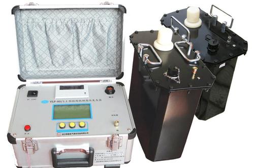
Switch Characteristic Tester
The Switch Characteristic Tester (also known as High Voltage Switch Mechanical Characteristic Tester, Circuit Breaker Dynamic Characteristic Tester) is a high-precision diagnostic instrument specifically used in power systems to detect the mechanical dynamic characteristics of high-voltage circuit breakers. Its core function is to evaluate the health status of the operating mechanism and arc extinguishing chamber by quantifying key parameters such as opening/closing time, speed, stroke, synchronization, and bounce during circuit breaker installation and commissioning, preventive testing, and troubleshooting, so as to prevent catastrophic accidents such as failure to operate and maloperation.
I. Working Principle
The instrument uses a high-performance microprocessor (single-chip microcomputer or industrial computer) as its core, working in conjunction with high-precision sensors and signal processing circuits:
Signal acquisition: The open/close status of circuit breaker contacts is collected through contact signal lines, and the mechanical motion signals of the moving contact are collected in real time through displacement sensors (linear/rotary/acceleration sensors).
Action triggering: The instrument has a built-in adjustable DC power supply (DC 0~270V/15~20A) to directly drive the opening/closing coil (internal trigger), or collects an external operating power signal as the timing starting point (external trigger).
High-speed sampling and calculation: Taking the moment the coil is energized as the timing starting point, the microprocessor samples contact status changes and displacement data at high speed, accurately calculates parameters such as time, speed, and stroke, and plots the "stroke-time" characteristic curve and coil current waveform.
II. Core Test Items
Test Category Specific Parameters Typical Accuracy/Resolution
Time parameters Inherent opening/closing time, same-phase synchronization, inter-phase synchronization, reclosing time (open-close-open), metal short time, no-current time Resolution 0.1ms, error ±0.1ms
Speed and stroke Just-opening/just-closing speed, maximum speed, average speed, total stroke, opening distance, overtravel, overshoot stroke Speed resolution 0.01m/s, stroke resolution 0.1mm
Bounce characteristics Closing bounce count, bounce time, opening rebound amplitude —
Coil characteristics Opening/closing coil current waveform, operating voltage, coil resistance Current resolution 0.01A
Low-voltage operation Minimum reliable operating voltage (automatic voltage rise test from 30%~100% rated voltage) —
III. Key Points for Model Selection
Number of contact channels (primary parameter):
Basic type (6-channel contact): Suitable for routine testing of vacuum and minimum-oil switches at 35kV and below
General type (12-channel contact): Supports synchronous detection of 6 main contacts + 6 auxiliary contacts, suitable for 10kV~500kV circuit breakers and GIS combined electrical apparatus, and is the mainstream model for power operation and maintenance
Special type: Graphite contact type (suitable for Siemens/ABB graphite contact SF6 switches), closing resistor type (500kV/750kV ultra-high voltage circuit breakers), dynamic resistance type (synchronously collects dynamic resistance curves)
Measurement accuracy and range:
Time measurement: Range ≥2000ms, resolution 0.1ms, error ≤±0.1ms
Speed measurement: Range 0~20m/s, resolution 0.01m/s, error ≤±(1% reading+0.1)m/s
Stroke measurement: Linear sensor range 50mm, rotary sensor corresponds to 0~1000mm, resolution 0.1mm
Anti-interference capability (key for on-site testing): The live operation of bypass busbars in substations generates strong electromagnetic interference. The equipment must have anti-interference designs such as photoelectric isolation to ensure stable operation near live busbars in 500kV substations.
Built-in operating power supply: Prefer models with a built-in DC 0~270V/15~20A digitally adjustable power supply, so that low-voltage operation tests can be completed without an external voltage regulator, greatly simplifying on-site wiring.
Sensor adaptability: The equipment should support multiple types such as linear sensors (vacuum switches), rotary sensors (SF6 switches), and acceleration sensors, and provide universal brackets for easy installation.
Data processing and output: Equipped with large-screen touch display, built-in printer, USB/U disk data storage, and real-time clock archiving functions; high-end industrial computer models support Windows system, WIFI transmission, and connection to State Grid MES systems.
Portability: The overall weight is recommended to be ≤10kg for easy outdoor transport and climbing operations.
IV. Usage Method (Standard Procedure)
Pre-test preparation:
Confirm that the circuit breaker has been de-energized and tested for absence of voltage, disconnect the control power supply and energy storage power supply, and hang a "Do Not Close" sign
Check that the ambient temperature is -10℃~50℃ and humidity is ≤85%RH
Reliably ground the instrument main unit
Wiring operation:
Contact wires: Connect according to the "one phase, three wires" principle, with the common terminal grounded (yellow, green, and red correspond to phases A, B, and C; the black wire connects to the common terminal)
Sensors: For vacuum switches, use a linear sensor attached to the vertical conductive rod; for SF6 switches, use a rotary sensor installed on the main shaft or crank arm, ensuring firm installation and smooth follow-up movement
Control wires: For internal triggering, connect the instrument's opening/closing output to both ends of the coil (the original operating power supply in the switchgear must be disconnected); for external triggering, only collect signals and do not output power
Parameter setting:
Select switch type (vacuum/SF6/oil), sensor type, and trigger mode (internal trigger/external trigger)
Enter nameplate parameters such as contact opening distance and overtravel
Set rated operating voltage and test duration (single opening/single closing generally 250ms, reclosing 500~2000ms)
Set the speed definition interval (for example, just-opening/just-closing speed usually takes the average speed within 10ms before and after contact separation/contact)
Test execution:
Single opening test: Place the circuit breaker in the closed position, trigger the opening command, and record opening time, just-opening speed, and bounce data
Single closing test: Place the circuit breaker in the open position, trigger the closing command after energy storage, and record closing time, just-closing speed, total stroke, and overtravel
Reclosing test: Select "close-open" or "open-close-open" mode, set the time interval, and record metal short time and no-current time
Low-voltage operation test: Adjust the output voltage to automatically rise from 30%~100% rated voltage, and test the minimum reliable operating voltage
Data analysis:
Check the time-stroke curve, speed curve, and contact waveform to determine whether the contact movement is smooth
Verify key indicators: whether three-phase synchronization (vacuum ≤2ms, SF6 ≤3ms) and bounce time (vacuum ≤2ms) meet manufacturer standards or specifications such as DL/T 846.3 and GB 1984
Compare with historical data; if the deviation exceeds ±10%, mechanical faults need to be investigated
Post-test finishing: First remove the control circuit wiring, then remove the contact wires and sensors; manually open and close 3 times to confirm the mechanism is normal before restoring power supply.
V. Common Troubleshooting
Fault Phenomenon Possible Cause Remedy
Data fluctuation/instrument crash Strong electromagnetic interference, poor grounding Ensure reliable grounding of the instrument; stay away from live busbars or use an anti-interference model
Abnormal speed data Loose sensor installation, wrong sensor type selected Refix the sensor to ensure coaxial alignment; confirm the sensor type setting is correct
Unable to trigger switch action Internal trigger voltage set too low, coil wiring reversed, external power supply not connected Increase output voltage; check wiring polarity; confirm external power supply is normal during external triggering
Abnormally high bounce count Contact wear, buffer failure, insufficient overtravel Check contact condition; adjust overtravel; investigate mechanism jamming
Abnormal coil current waveform Inter-turn short circuit of coil, core jamming Measure coil resistance; check whether the core moves smoothly
VI. Precautions for Use
Long-time DC output is strictly prohibited: The internal operating power supply is a short-time working power supply, and the test duration is generally set within 250ms; after voltage calibration is completed, be sure to set the test duration back to 250ms, otherwise long-time DC output will burn out the opening/closing coil.
Sensor installation specifications: When installing a linear sensor, reserve a buffer length of about 15mm to ensure that the sensor will not be damaged by overshoot stroke during opening and closing.
Reliable grounding: Before connecting the contact wires, first connect the instrument casing to earth to discharge induced voltage and protect the instrument and personal safety.
Environmental requirements: Avoid testing in thunderstorms or environments with humidity >90%; the operating temperature is usually -10℃~50℃.
Regular calibration: It is recommended to calibrate once a year to ensure that the accuracy of parameters such as time, speed, and stroke meets standards.
As a core tool for diagnosing the mechanical state of circuit breakers, the Switch Characteristic Tester requires comprehensive consideration of six dimensions during model selection: number of contact channels, measurement accuracy, anti-interference capability, built-in power supply, sensor adaptability, and portability. If you have a specific application scenario (such as voltage level, switch type, whether graphite contact testing is required), I can help you further refine the model selection recommendations.