Partial Discharge Detector
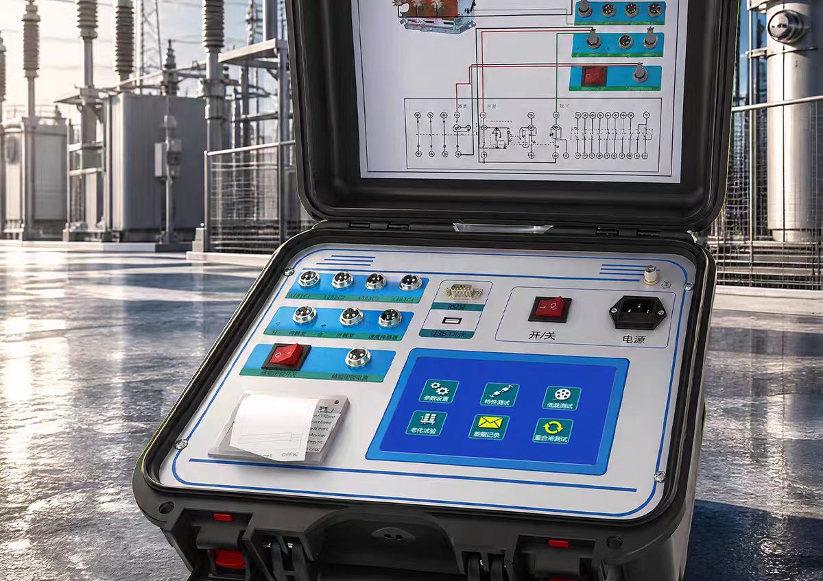
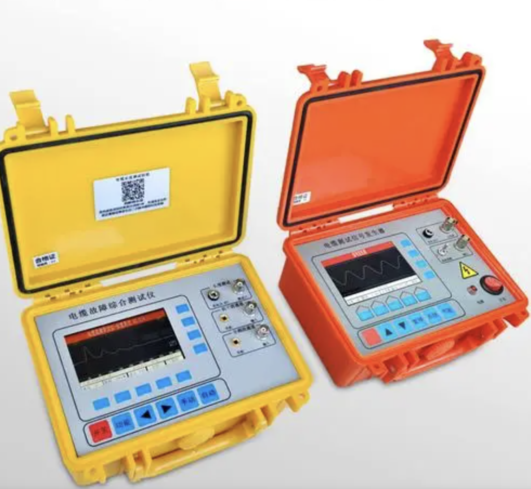
A partial discharge detector (PD detector) is a professional instrument used to detect insulation defects in high-voltage electrical equipment. By capturing signals such as electromagnetic waves, ultrasonic waves, and transient earth voltages generated by partial discharges in the insulation system, it enables quantitative testing of equipment insulation status and defect location. It is a core tool for the transition of power equipment from "periodic maintenance" to "condition-based maintenance."
What is Partial Discharge
According to the definition in the IEC 60270 standard, partial discharge (PD) refers to localized dielectric discharge occurring in a part of a solid or liquid electrical insulation system under high-voltage field stress. Defects such as bubbles, cracks, and metallic impurities inside the insulation can trigger weak discharges under long-term high-voltage electric fields. Initially, the energy is extremely small, but it continuously erodes the insulation structure, potentially leading to equipment breakdown or even large-scale power outages.
Main Detection Technologies
Partial discharge detectors typically employ a combination of multiple detection technologies, enhancing detection accuracy and reliability through signal complementarity:
Table
Download as Table
Export as Image
Detection Method Principle Features
Pulse Current Method (ERA Method) Based on high-frequency pulse current measurement, capable of measuring apparent discharge quantity, discharge repetition rate, and other parameters Complies with IEC 60270 standard, with sensitivity up to 0.02 pC
Ultra-High Frequency Method (UHF) Detects electromagnetic wave signals in the 300 MHz to 3 GHz frequency band Strong anti-interference capability, can penetrate metal enclosures, suitable for enclosed equipment such as GIS
Acoustic Emission Method (AE) Detects acoustic wave signals in the 20 kHz to 300 kHz frequency band Unaffected by electromagnetic interference, suitable for precise location of discharge points
Transient Earth Voltage Method (TEV) Detects transient earth voltage signals in the 3 MHz to 100 MHz frequency band Suitable for live detection of metal-enclosed equipment such as switchgear
High-Frequency Current Transformer Method (HFCT) Detects pulse currents in grounding wires via high-frequency current transformers Non-intrusive installation, suitable for online monitoring of cables
Acoustic Imaging Technology Uses an array of acoustic pressure sensors to convert ultrasonic signals into visual images Non-contact rapid location, as intuitive as a "thermal imager"
Instrument Types
Table
Download as Table
Export as Image
Type Features Applicable Scenarios
Handheld Portable Lightweight (0.7 kg to 3.5 kg), battery life ≥8 hours, integrated with multiple sensors Daily live patrol inspection, fault troubleshooting
Benchtop Detection System Multi-channel synchronous acquisition, comprehensive functions, supports PRPD/PRPS pattern analysis Factory tests, acceptance tests, laboratory testing
Online Monitoring System Fixed installation, 7×24 hour real-time monitoring, supports remote transmission and intelligent alerts Unattended substations, long-term monitoring of critical equipment
Key Technical Parameters
Table
Download as Table
Export as Image
Parameter Item Typical Specification
Detection Sensitivity Pulse current method can reach 0.02 pC to 0.1 pC; non-intrusive methods such as UHF/TEV/HFCT can reach ≤0.5 pC under laboratory conditions
Sampling Rate Up to 2 GS/s, commonly 100 MS/s to 200 MS/s
Sampling Resolution 8-bit, 12-bit, 14-bit, or 16-bit
Linearity Error Typically ≤±10%
Location Accuracy Acoustic imaging or UHF/AE fusion location accuracy can reach <1 cm to ≤1 m
Synchronization Method Supports internal, external, wired, and wireless synchronization, with phase accuracy ≤0.1°
Testable Capacitance Range 6 pF to 250 μF
Intelligent Analysis Functions
Modern PD detectors are equipped with high-performance digital processing chips and intelligent analysis systems. Core analysis tools include:
PRPD Pattern (Phase-Resolved Partial Discharge Pattern): Presents the correlation between discharge pulse amplitude and power frequency voltage phase in a two-dimensional form, determining whether the discharge is related to 50 Hz or 100 Hz power frequency
PRPS 3D Pattern (Phase-Resolved Pulse Sequence Pattern): Adds a time dimension to fully reconstruct the variation of discharge characteristics over time
Automatic Discharge Type Recognition: Combined with AI algorithms, it can automatically identify typical discharge types such as free metallic particles, floating potential bodies, insulation voids, metallic protrusions, and corona discharge
3PARD Three-Phase Amplitude Relation Diagram: Can separate multiple simultaneous partial discharge sources for more reliable fault detection
Applicable Equipment
Power Transformers: Insulation status detection and location for oil-immersed and dry-type transformers
GIS/GIL: Internal discharge detection for gas-insulated switchgear
Switchgear: Live patrol inspection of complete distribution equipment
Power Cables: Live detection and diagnostic testing for 66 kV to 500 kV cable lines
Generators/Motors: Insulation monitoring for rotating machinery
Instrument transformers, surge arresters, bushings, capacitors, etc.