

When performing AC withstand voltage tests on large generators, power cables, GIS, and other equipment with large capacitance, power-frequency test equipment is often bulky and heavy, making on-site transportation and power supply configuration difficult. Some technicians have attempted to use DC withstand voltage instead, but the electric field distribution under DC voltage differs from that under power-frequency conditions, resulting in limited detection of insulation defects. How to obtain an equivalent test effect close to power frequency under on-site conditions while reducing equipment capacity requirements is a specific problem faced by many technical engineers.
According to DL/T 417-2006 and other relevant standards, using 0.1Hz very low frequency AC voltage for withstand voltage testing of capacitive test specimens allows the specimen to withstand voltage stress close to power frequency at a lower frequency. Due to the reduced frequency, the capacity and volume of the test equipment can be significantly reduced, making it convenient for on-site use. This method is suitable for handover and preventive tests of generator stator windings, power cables, capacitors, and other equipment.
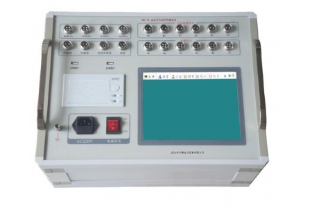
The device adopts a dual-meter display design for output voltage and output current: the pointer meter is used to observe the trend of voltage and current changes, while the digital meter displays the positive and negative peak values of voltage and current, making it easy to read specific values. The equipment has a built-in overvoltage protection function. When the test voltage exceeds 1.1 times the set value, the device automatically cuts off the output and issues a prompt, preventing the test specimen from being damaged by abnormal voltage. The output waveform is 0.1Hz very low frequency AC, with a peak voltage of up to 90kV and a load capacitance range covering 0.5μF and below, which can meet the test needs of most generator and cable specimens.
After wiring is completed, it is recommended to first conduct a no-load voltage rise test to confirm that the voltage and current displays are normal. During the voltage rise process, adjustment should be made slowly while observing the reading changes of the pointer meter and digital meter. After the test is completed, wait for the equipment to automatically discharge completely before performing disconnection operations. For specimens with different capacitance values, test parameters should be selected according to the rated load capacity of the equipment to avoid prolonged overload operation.

