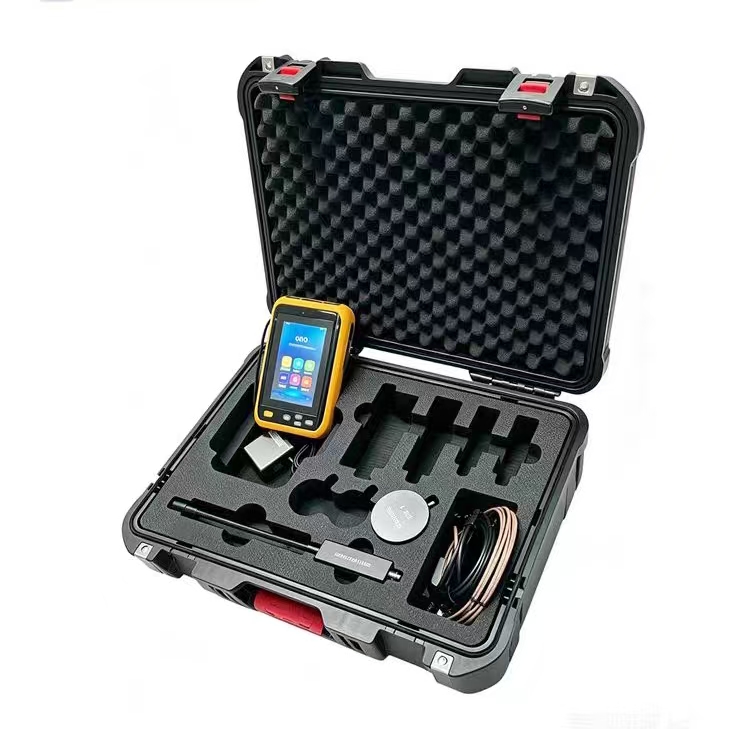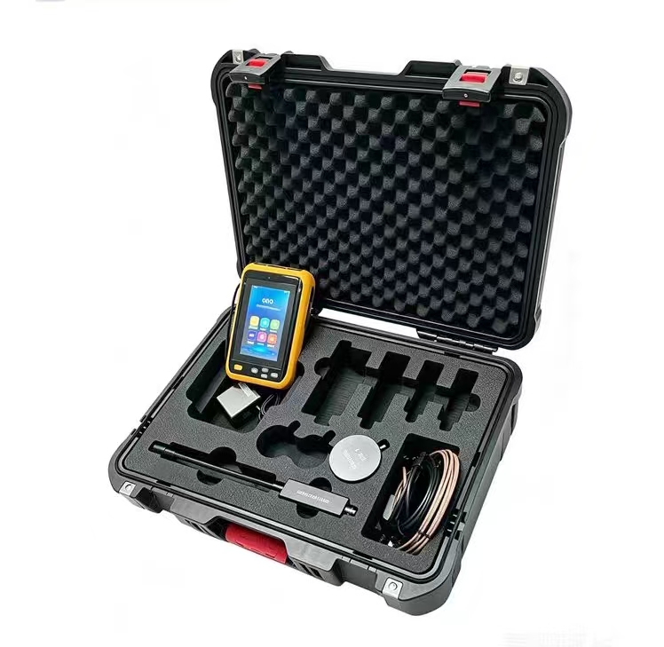
Very Low Frequency (VLF) Withstand Voltage Test
Very Low Frequency (VLF) withstand voltage test is an alternative to power frequency withstand voltage test, using AC high voltage at 0.1Hz (or lower frequency) to assess the insulation strength of power equipment. It is widely used for on-site withstand voltage testing of large capacitive equipment such as cables, generators, and motors.
Basic Principle
The 50Hz power frequency AC voltage is converted to DC through rectification and filtering, then inverted to 1kHz AC voltage, amplitude-modulated by a 0.1Hz sine wave oscillator, and finally outputs a 0.1Hz high-voltage sine wave (or cosine square wave).
Since cables are large capacitive equipment, traditional power frequency withstand voltage generates a large charging current, requiring high capacity of the test power supply. However, at very low frequencies, the capacitive current is significantly reduced (proportional to frequency), and while ensuring equivalent insulation stress, the size and weight of the test equipment can be reduced to about 1/500 of traditional power frequency equipment, making it very suitable for on-site operations.
Core Advantages
Table
Download as Table
Export as Image
Comparison Item VLF (0.1Hz) Power Frequency (50Hz) DC Withstand Voltage
Equipment Size Small, portable Large, bulky Medium
Damage to Aged Insulation Small Relatively large May introduce space charge
Equivalence Good equivalence with power frequency Reference method Risk of "false pass"
Defect Detection Capability Can expose water tree aging, mechanical damage Comprehensive Difficult to detect certain defects
Compared to DC withstand voltage, VLF AC voltage can periodically change the direction of the electric field, making it easier to expose defects such as water tree aging and mechanical damage inside the insulation, avoiding the "false pass" phenomenon that may occur in DC withstand voltage.
Applicable Scope
Power cables: Cross-linked polyethylene (XLPE) insulated power cables rated 35kV and below (not applicable for 110kV and above)
High-voltage generators: More effective than power frequency for detecting end-winding insulation defects
Large motors: Insulation assessment during commissioning, major overhaul, and partial rewinding
Test Standards and Parameters
Mainly based on the following standards:
GB 50150-2016 "Standard for Acceptance Tests of Electric Equipment in Electrical Installations"
DL/T 596-2021 "Regulations for Preventive Tests of Power Equipment"
DL/T 849.4-2024 "General Technical Specifications for Special Test Instruments for Power Equipment - Part 4: Very Low Frequency High Voltage Generator"
Acceptance Test Parameters (GB 50150-2016)
Table
Download as Table
Export as Image
Rated Voltage U₀/U (kV) Test Voltage Duration
1.8/3 3U₀ (5kV) 60min
6/10 3U₀ (18kV) 60min
8.7/10 3U₀ (26kV) 60min
12/20 3U₀ (36kV) 60min
26/35 3U₀ (78kV) 60min
Preventive Test Parameters
There are differences in regulations across different regions:
DL/T 596-2021: Test voltage 2.5U₀, duration 15~60min
North China Power Grid regulations: Test voltage 2.1U₀, applied for 5min
Jiangsu Provincial Electric Power Company regulations: Test voltage 3U₀, applied for 20min
Considering that you are in the Jiangsu region, for preventive tests, you can refer to the Jiangsu Provincial Electric Power Company regulations, i.e., applying 3U₀ for 20 minutes without breakdown is considered qualified.
Test Operation Procedure
Disconnect the equipment under test: Disconnect all electrical equipment connected to the test cable
Insulation resistance pre-check: Use a 5000V or 10000V megohmmeter to measure and record the insulation resistance of each phase separately
Reliable grounding: The test equipment should be reliably grounded using bare copper wire
Connect the test object: Use a flexible connecting cable to connect the VLF high voltage generator to the test cable
Set parameters: Set the test frequency (0.1Hz), test voltage, test duration, and overcurrent/overvoltage protection values
Voltage application: Slowly increase the voltage, closely monitor the high-voltage circuit, and listen for any abnormal sounds
Stabilize voltage and timing: Start timing after reaching the test voltage, and record voltage and current values
Reduce voltage and shut down: After the test duration, first reduce the voltage to zero, then cut off the power
Discharge and disconnect: Use a discharge rod to fully discharge the test object before disconnecting
Acceptance Criteria
No destructive discharge (no breakdown) throughout the entire withstand voltage process is considered qualified
No upper limit for leakage current is specified
After the test, the insulation resistance should be re-measured and compared with the pre-test data for analysis
Abnormal Handling
During voltage application and withstand voltage testing, if any of the following phenomena occur, stop increasing voltage, reduce voltage, and cut off power immediately to investigate the cause:
Significant fluctuation of the voltmeter pointer
Rapid increase in ammeter indication
Voltage remains basically unchanged or even decreases when continuing to increase voltage with the voltage regulator
The test cable emits odor, smoke, or abnormal sounds
Flashover occurs
If caused by air humidity or surface contamination, clean and dry the surface before retesting. If caused by insulation defects, it is judged as unqualified. After an interruption, the full-duration test must be restarted; it is not allowed to merely "make up the time".