

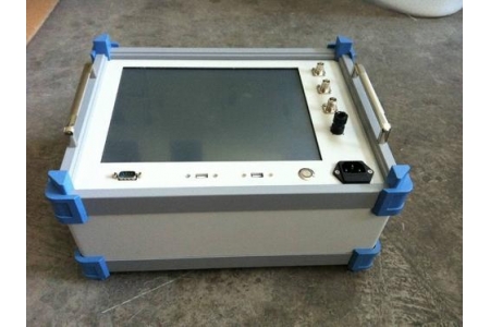
The Very Low Frequency (VLF) withstand voltage test is a test method that uses extremely low frequency (typically 0.1Hz, 0.05Hz, or 0.02Hz) AC high voltage to assess the insulation strength of power equipment. It is an alternative to the traditional power frequency (50Hz) withstand voltage test, particularly suitable for on-site insulation testing of large capacitive loads such as cables and generators. While maintaining equivalent insulation assessment effectiveness, it significantly reduces the capacity requirements of the test equipment.
Working Principle
The core principle of the VLF withstand voltage test lies in utilizing the proportional relationship between frequency and capacitive current:
Reducing capacitive current: Cables, generator stator windings, etc., are large capacitive loads. According to the capacitive current formula I = 2πfCU, at power frequency 50Hz, the capacitive current of long cables is significant. By reducing the frequency from 50Hz to 0.1Hz (a reduction of 500 times), the capacitive current is correspondingly reduced by 500 times, and the power supply capacity required by the test equipment is only about 1/500 of that at power frequency.
Equivalent insulation assessment: Both theory and practice have proven that 0.1Hz VLF AC voltage has good equivalence with power frequency AC voltage in insulation assessment. AC voltage can periodically change the direction of the electric field, effectively exposing defects such as mechanical damage and water tree aging inside the insulation, avoiding the "false pass" phenomenon that may occur in DC withstand voltage tests.
Equipment implementation: The VLF high-voltage generator uses digital frequency conversion technology and a microcomputer control system to rectify and invert the power frequency supply, generating a 0.1Hz sinusoidal high-voltage output, achieving full automation of voltage boosting, reduction, measurement, and protection.
Comparison with Power Frequency and DC Withstand Voltage Tests
Table
Download as Table
Export as Image
Comparison Item Power Frequency Withstand Voltage (50Hz) VLF Withstand Voltage (0.1Hz) DC Withstand Voltage
Equipment Capacity Requirement Extremely large Extremely small (about 1/500 of power frequency) Relatively small
Damage to Insulation Normal Extremely small, no damage Relatively large, harmful polarized charges enter the dielectric
Defect Detection Capability Good Good, more sensitive to end insulation defects Prone to "false pass", cannot reflect AC operating conditions
On-site Portability Poor, bulky equipment Good, small size and light weight Relatively good
Applicable Objects Small-capacity equipment Large capacitive equipment (cables, generators) Gradually being replaced
Main Application Scenarios
Power cable withstand voltage test: The most typical application scenario. Applicable to new installation acceptance tests, preventive tests of in-service cables, and post-repair retests for 35kV and below cross-linked polyethylene (XLPE) insulated power cables.
Generator stator winding withstand voltage: The 0.1Hz VLF has better detection capability for generator end insulation defects than power frequency. Because at power frequency, the capacitive current flowing out of the stator bars produces a large voltage drop on the semiconductor anti-corona layer, reducing the actual voltage borne by the end insulation; at VLF, this voltage drop is significantly reduced, resulting in higher voltage on the end insulation, making it easier to detect defects.
High-voltage motor insulation testing: Acceptance and preventive tests for large motor stator windings.
Insulation defect trend assessment: Through comprehensive analysis of current changes during the withstand voltage process, withstand voltage holding time, and dielectric loss tangent (tanδ), the degree of insulation aging and potential weak points can be preliminarily judged.
Test Method and Procedure
Taking 35kV and below XLPE cables as an example, the typical test procedure is as follows:
Pre-test preparation: Disconnect all electrical equipment connected to the test object, and reliably ground the test equipment using bare copper wire.
Insulation resistance pre-check: Use a 10000V megohmmeter to perform insulation resistance tests on each phase of the test cable. The VLF withstand voltage test can only be carried out after passing.
Set test parameters:
Peak cable test voltage: Umax = 3Uo (Uo is the rated phase voltage of the cable). For example, for a 10kV cable, Uo = 10/√3 ≈ 5.77kV, then Umax = 3 × 5.77 ≈ 17.32kV.
Peak generator test voltage: Umax = √2 × β × K × Uo, where β is the equivalence coefficient between 0.1Hz and 50Hz (taken as 1.2), K is taken as 1.3-1.5 (generally 1.5), and Uo is the rated voltage of the generator stator winding.
Test duration: For new cable acceptance tests, it is usually 60 minutes.
Voltage boosting and monitoring: Close the power supply to start boosting, closely monitor the high-voltage circuit, and listen for any abnormal sounds from the test object. Start timing after reaching the test voltage.
Result determination: After the test time is completed, the equipment automatically stops. If no destructive discharge occurs, the withstand voltage test is considered passed.
Abnormality Judgment and Handling
During the voltage boosting and withstand voltage process, if any of the following phenomena occur, stop boosting immediately, reduce voltage, and cut off power to investigate the cause:
Output waveform is abnormally distorted, and current increases abnormally
Voltage is unstable; the voltage regulator continues to boost but the voltage remains basically unchanged or even drops
The test cable emits an odor, smoke, or abnormal sounds
Flashover occurs
If it is confirmed that the insulation of the test object is weak, it is judged as unqualified; if it is caused by air humidity or surface contamination, clean and dry the surface and retest. After the test is interrupted and power is restored, the full-duration withstand voltage test should be restarted, not merely "make up the time".
Applicable Standards
DL/T 849.4 "General Technical Conditions for Special Test Instruments for Power Equipment - Part 4: Very Low Frequency High Voltage Generator"
IEEE Std. 400.2-2013 "IEEE Guide for Field Testing of Shielded Power Cable Using Very Low Frequency (VLF)"
Industry standard "Test Method for Very Low Frequency (0.1Hz) Withstand Voltage of 35kV and Below Cross-linked Polyethylene Insulated Power Cables"
Selection Key Points
Output voltage range: Select according to the voltage level of the equipment under test, commonly covering 0-90kV.
Output frequency: Prioritize models that support multiple adjustable frequencies of 0.1Hz, 0.05Hz, and 0.02Hz. The lower the frequency, the larger the capacitive load that can be driven.
Load capacity: At 0.1Hz, the typical load capacity is 1.1μF, and at 0.05Hz, it is 2.2μF. Ensure it can cover the total capacitance of the cable under test.
Protection functions: Should have multiple protections such as overvoltage, overcurrent, and zero-position protection, with an action time of ≤20ms.
Portability: Fully electronic design, small size, light weight, suitable for outdoor and on-site operations.
Data management: Support test data storage, automatic report printing, USB export, and other functions.

