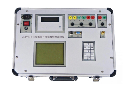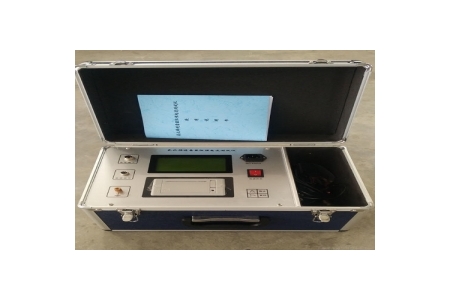
Switch Characteristic Tester
The Switch Characteristic Tester (often referred to as the "High-Voltage Switch Mechanical Characteristics Tester") is a specialized precision instrument used in power systems to detect the mechanical performance of high-voltage circuit breakers. Since high-voltage circuit breakers undertake the dual tasks of control and protection in the power grid, their mechanical characteristics directly affect the safe operation of the entire power system.
Core Functions and Measurement Parameters
This instrument comprehensively evaluates the working status of the circuit breaker's operating mechanism and arc extinguishing chamber through high-precision sensors and a high-speed data acquisition system. A single switching operation can synchronously obtain the following core parameters:
Time Parameters: Precisely measure the inherent opening/closing times of 12 break contacts, phase-to-phase and inter-phase non-synchronism, closing/opening bounce time and count, and reclosure time (open-close-open), etc.
Speed and Travel Parameters: Measure the speed at contact separation/closure, maximum speed, average speed over specified time intervals, as well as the total travel of the moving contact, contact travel (contact gap), overtravel, and overtravel or rebound travel.
Coil Current and Operating Voltage: Record the current waveform and resistance of the opening/closing coils, automatically perform low-voltage operation tests on the circuit breaker, and determine whether there are hidden dangers such as mechanism jamming or spring fatigue.
⚙️ Working Principle and Hardware Features
Modern switch characteristic testers mostly use high-performance microprocessors (such as embedded industrial computers or DSP) combined with high-speed sampling technology. The instrument typically integrates an adjustable DC operating power supply (e.g., DC 6-270V/20A), allowing direct operation of the circuit breaker without an external secondary power supply. By connecting displacement sensors (linear, rotary, or laser sensors) and break contact signal lines to the moving contact, the instrument performs high-speed data acquisition while issuing opening/closing commands, thereby accurately reproducing the "travel-time" characteristic curve and coil current waveform of the switching operation.
Applicable Scenarios and Equipment Types
Switch characteristic testers are widely used in installation commissioning, preventive tests, and maintenance of power systems. They are suitable for various voltage levels (e.g., up to 500kV) of low-oil, multi-oil, vacuum, SF6 (sulfur hexafluoride) circuit breakers, and GIS combined appliances, both domestically and internationally.
In addition to high-voltage switch mechanical characteristic testers, broadly defined switch testing equipment also includes:
Transformer On-Load Tap Changer Tester: Specifically used to measure the transition time, transition resistance, and transition waveform of transformer on-load tap changers.
Switch Loop Resistance Tester: Uses a large current (e.g., 100A or 200A) DC voltage drop method to measure the contact resistance of switch contacts and conductive loops. Anti-interference capability: Strong spatial electromagnetic interference often exists at substation sites. When selecting a model, special attention should be paid to the instrument's anti-interference performance to ensure stable operation near 500kV live busbars, avoiding data fluctuations or system crashes.
Sensor Matching: It is necessary to select matching sensors and mounting brackets according to the type of switch to be tested (e.g., linear sensors for vacuum switches, rotary sensors for SF6 switches) to ensure easy installation and accurate data.
Data Analysis and Storage: A high-quality tester should not only display data and waveforms on the same screen but also have envelope comparison analysis and vibration frequency analysis functions, and support USB export and PC software for generating standardized test reports.
Safety Regulations: On-site testing must strictly comply with safety regulations, confirming that the circuit breaker is de-energized, isolated, and reliably grounded. When using the built-in power supply, the original operating power supply of the switchgear should be disconnected to prevent back-feeding.