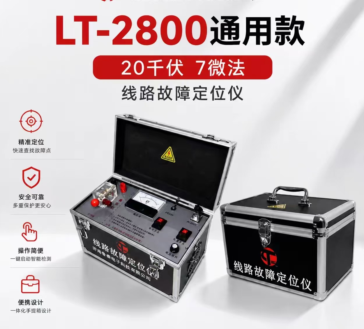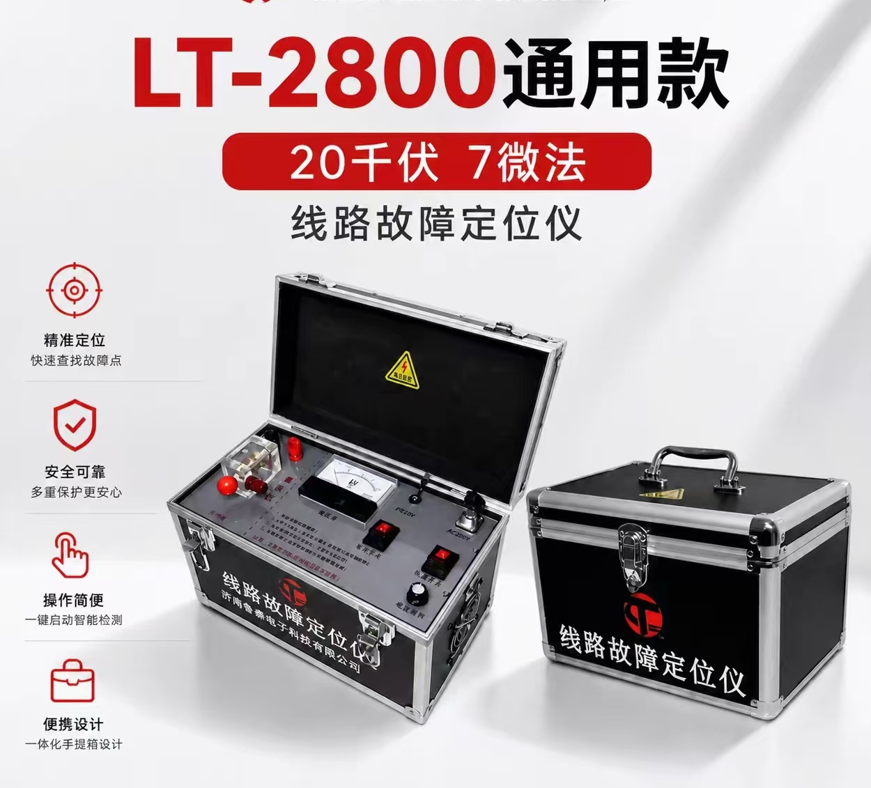
Zinc Oxide Arrester Tester
The Zinc Oxide Arrester Tester (MOA Tester) is a precision instrument specifically designed to detect the electrical performance of Zinc Oxide Arresters (MOA). By measuring key parameters such as total current, resistive current, and their harmonics, it promptly identifies dangerous defects such as internal insulation moisture and valve disc aging in arresters. It is a core tool for condition-based maintenance of lightning protection equipment in power systems.
Under normal operating voltage, a Zinc Oxide Arrester mainly conducts capacitive current, with a very small resistive current component. When the valve discs age or internal moisture occurs, the resistive current component increases significantly. The core approach of the tester is to "separate the resistive current":
By obtaining the reference voltage signal from the secondary side of a voltage transformer (PT) or an induction plate, and simultaneously collecting the arrester leakage current signal using a current clamp or wiring method, the Fourier harmonic analysis algorithm is used to decompose the total current into resistive and capacitive components, precisely extracting the fundamental resistive current and its 3rd to 9th harmonic content, thereby determining the health status of the arrester.
Download as Table
Export as Image
Parameter Description
Total Current Total leakage current of the arrester, including fundamental RMS value and peak value
Resistive Current Core indicator reflecting valve disc aging and moisture degree, including fundamental, 3rd/5th/7th/9th harmonics
Capacitive Current Main current component during normal operation
Power Frequency Reference Voltage and its harmonic components
Active Power Arrester power consumption
Phase Difference Phase angle between voltage and current
Test Host: Built-in high-performance ARM processor and DSP floating-point unit, equipped with a color touchscreen, responsible for signal acquisition, harmonic analysis, and data display
Voltage Collector: Used to obtain the reference voltage signal, supporting wired direct connection to the PT secondary side or wireless induction plate method
Current Sensor: Clamp-type current transformer or wired sensor, collecting the leakage current from the arrester grounding down-conductor
Built-in Lithium Battery: No external power supply needed, suitable for field occasions without power
Data Storage and Transmission Module: Supports USB flash drive export, Bluetooth APP control, wireless data upload
Key Technical Parameters
Table
Download as Table
Export as Image
Parameter Typical Range
Total Current Measurement Range 0~20mA (expandable to 30mA)
Resistive Current Measurement Range 0~20mA
Voltage Acquisition Range 10V~250V (expandable to 500V)
Current Resolution 1μA
Current Measurement Accuracy ±(reading×2%+5μA)
Voltage Measurement Accuracy ±(reading×2%+0.2V)
Harmonic Analysis Fundamental, 3rd~9th harmonics
Electric Field Strength Measurement 30kV/m~300kV/m (optional)
Continuous Working Time 6~8 hours
Working Temperature -10℃~+50℃
Host Weight Approximately 1.0kg~7.5kg (varies by model)
Voltage Reference Sampling Methods
The tester needs to obtain the system voltage as a reference. The mainstream supported methods are as follows:
Table
Download as Table
Export as Image
Method Features
Wired Synchronization Direct connection to PT secondary side, highest accuracy, transmission distance about 40 meters
Wireless Synchronization Split-type collector wireless transmission, distance up to over 1500 meters, flexible operation
Induction Plate Sampling Uses electric field induction to obtain reference voltage, no need to contact high-voltage circuit, safe and convenient
No-Voltage Method Calculates voltage reference through software-set angle or current analysis method, suitable for scenarios where voltage cannot be obtained
Core Functional Features
Three-Phase Simultaneous Testing: Supports simultaneous testing of A, B, C three-phase current and voltage, completing three-phase detection with one wiring setup, greatly improving efficiency
Inter-Phase Interference Compensation: Built-in automatic edge compensation algorithm, overcoming the influence of three-phase mutual interference at 220kV and above voltage levels, accurately measuring the resistive current of edge-phase arresters
Digital Filtering Anti-Interference: Adopts harmonic analysis and digital filtering technology, effectively filtering out on-site corona and electromagnetic interference
Real-Time Waveform Display: Large screen displays true voltage and current waveforms on the same screen, making resistive fundamental proportion and harmonic anomalies intuitively visible
Data Storage and Management: Built-in large-capacity storage, supports power-off protection, USB flash drive export of Word files, Bluetooth APP remote control
Live/Offline Compatibility: Supports both live detection during operation and offline maintenance and laboratory acceptance testing
Standard Testing Process
Pre-Test Preparation: Confirm the operating status of the arrester, set up safety barriers
Voltage Sampling: Connect the voltage collector to the PT secondary side, or place the induction plate to obtain reference voltage
Current Sampling: Clamp the current clamp onto the arrester grounding down-conductor, or connect wires to both ends of the discharge counter
Parameter Setting: Select synchronization method, set the phase to be tested and test parameters
Start Testing: The instrument automatically collects signals, performs harmonic analysis, and displays total current, resistive current, capacitive current, and various harmonics
Data Analysis: Compare with historical data and standard thresholds to determine the health status of the arrester
Data Storage: Save test data, export reports
Applicable Scenarios
Substation Live Inspection: Non-outage detection of arrester status during routine operation and maintenance
Line Arrester General Survey: Batch detection of transmission and distribution line arresters
Handover Test and Factory Acceptance: Performance verification of newly installed arresters
Preventive Test: Regular detection of valve disc aging and insulation moisture trends
Fault Troubleshooting: Precise diagnosis when arresters are abnormal
Related Standards
DL/T 987-2005: General Technical Conditions for Zinc Oxide Arrester Resistive Current Testers
DL/T 474.5-2018: Guide for Implementation of On-Site Insulation Tests——Arrester Tests
DL/T 596: Preventive Test Code for Electric Power Equipment
🛒 Selection Key Points
Synchronization Method: Choose wired, wireless, or induction plate method according to site conditions; wireless method offers the most flexible operation
Measurement Accuracy: Focus on the accuracy of the fundamental resistive current, which directly affects the reliability of defect judgment
Three-Phase Simultaneous Testing Capability: Equipment with three-phase simultaneous testing and inter-phase interference compensation functions is more efficient
Portability: For frequent outdoor inspections, prioritize lightweight handheld design (around 1kg)
Battery Life: Built-in lithium battery with continuous working time of 6~8 hours is preferable
Data Management: Whether it supports USB flash drive export, Bluetooth APP, remote data upload, and other information-based functions