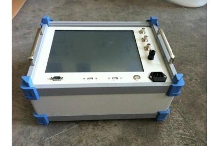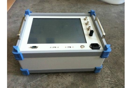
Transformer winding deformation tester frequency response method test device transformer winding deformation tester impedance method
The "frequency response method" and "impedance method" you mentioned are indeed the two most core technical means currently used in the power system to detect transformer winding deformation (such as distortion, bulging, displacement, etc.). With the development of technology, the current mainstream transformer winding deformation testers usually highly integrate these two methods to meet the detection needs under different working conditions.
Combined with relevant technical standards and industry practices, here is a detailed explanation of the principles, characteristics, and application specifications of these two testing methods:
1. Frequency Response Analysis (FRA)
The frequency response method is currently the most widely used non-destructive testing method, mainly based on the power industry standard DL/T 911-2016 and the international electrical standard IEC 60076-18.
Test principle: At higher frequencies, the transformer winding can be regarded as a passive linear two-port network composed of distributed inductance and capacitance. When the winding deforms, its internal distributed parameters inevitably change, causing the zero-pole points of the equivalent network transfer function to change. The instrument continuously changes the frequency of the external sinusoidal excitation source, measures the ratio of the voltage amplitude at the response end to that at the excitation end, and thus obtains the amplitude-frequency response curve of the winding.
Technical characteristics:
High sensitivity: Very sensitive to minor deformations of the winding (such as local distortion, bulging), and can accurately capture characteristic changes.
Frequency band diagnosis: Usually, the frequency band is divided into low frequency (1kHz~100kHz, reflecting inductance changes/inter-turn short circuits), medium frequency (100kHz~600kHz, reflecting local deformation), and high frequency (>600kHz, reflecting overall displacement or changes in capacitance to ground) for segmented analysis.
Analysis method: Mainly through horizontal comparison (comparison between the same model or three phases of the same transformer) and vertical comparison (comparison with factory or historical data) to judge the degree of deformation.
2. Low Voltage Short-Circuit Impedance Method (Impedance Method)
The impedance method is mainly based on the power industry standard DL/T 1093-2018.
Test principle: Reliably short-circuit the low-voltage side winding of the transformer, apply a low voltage (such as 220V or an external power supply) to the high-voltage side, and cause test current to flow through the winding. By accurately measuring the voltage and current at this time, the short-circuit impedance (mainly the leakage reactance component) is calculated. Since the leakage reactance is closely related to the geometric dimensions and relative positions of the winding, when the winding deforms, the leakage flux path changes, and the impedance value changes accordingly.
Technical characteristics:
Macroscopic judgment: Simple operation, good repeatability, can accurately reflect the overall change in impedance value before and after winding deformation, but is less sensitive to slight local deformation than the frequency response method.
Judgment criteria: Usually, the measured short-circuit impedance is compared with the factory nameplate value or historical data. A deviation within ±2% is considered normal; exceeding ±2% but less than ±3% indicates slight deformation; reaching ±3% or above indicates serious defects and requires disassembly inspection.
3. Technical Advantages of Modern Comprehensive Testers
Currently, mainstream equipment on the market (such as SF-8003A, KDRB-C, etc.) has achieved the integration of both methods and has the following intelligent features:
Dual standard compatibility: Meets the testing requirements of both the frequency response method (DL/T 911) and the impedance method (DL/T 1093), adapting to testing regulations for different voltage levels (such as large transformers of 66kV and above).
High precision and automation: Uses DDS digital frequency synthesis technology and high-speed A/D sampling, with frequency accuracy up to 0.001%. Supports three-phase automatic testing, automatic calculation of impedance error percentage, and automatic generation of Word test reports.
New sweep frequency impedance method: Some cutting-edge research and high-end equipment have introduced the "sweep frequency impedance method", which combines the high resolution of the frequency response method with the strong anti-interference capability of the impedance method, and can further infer the specific location and form of deformation faults.
💡 Further Assistance
The transformer winding deformation tester is key equipment for evaluating the mechanical integrity of transformers and preventing insulation breakdown accidents. May I ask what your specific needs are at present:
Equipment selection and parameter verification: Do you need me to sort out the core parameters that need to be focused on when purchasing such a "frequency response + impedance" dual-function tester, such as sweep frequency range (e.g., 10Hz~2MHz), sampling rate, and dynamic range?
On-site testing and wiring guidance: Do you need to understand the wiring specifications for the excitation/response ends during frequency response testing, or the specific operation steps for short-circuiting the low-voltage side and temperature compensation during impedance testing?
Spectrum analysis and fault diagnosis: After obtaining amplitude-frequency response curves or impedance deviation data in actual testing, do you need assistance in analyzing the shift of wave peaks/valleys to determine whether the winding has undergone axial displacement or radial deformation?